THROUGH-HOLE SOLDERING
PREPARATION OF CONDUCTORS
conductors
PREPARATION OF CONDUCTORS

The quality of solder terminations can be correlated to the preparation of the conductors prior to soldering.

Solderability can be significantly improved by the pre-tinning and thorough cleaning of all surfaces designated to be part of the completed solder termination. Pre-forming of component leads and other conductors reduces stresses in the solder joint and component body.

See Section 6.01 "Through-Hole Soldering, General Requirements", for common accept/reject criteria.
component leads conductors

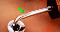
PREFERRED

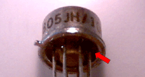
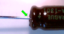
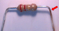
COMPONENT LEADS

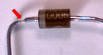
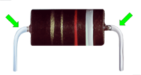
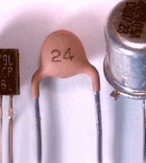
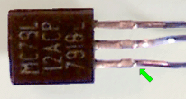
The component's leads have been tinned, formed and cleaned per engineering requirements. Gold plating has been removed. The spacing and radius of bends are within requirements. There is no mechanical damage to the component leads or body.

PREFERRED

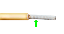
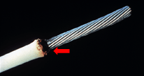
CONDUCTORS/WIRE

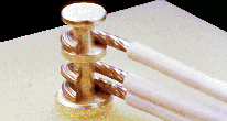
The conductors have been stripped, tinned, formed and cleaned per engineering requirements. There is no mechanical damage to the conductor or insulation, no reduced cross-section and individual strands are discernable.
termination areas terminations

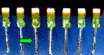
PREFERRED

TERMINATION AREAS/PWB

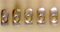
Termination areas have been tinned with hot-coated tin-lead solder or hot reflowed electro-deposited tin-lead solder prior to mounting of the parts. Gold plating has been removed.

PREFERRED

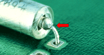
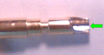
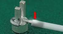
TERMINATIONS/MISCELLANEOUS

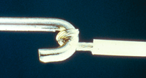
The terminations have been properly tinned, formed and cleaned in preparation of solder termination. The preparation of simple terminations, such as the hook and conductor termination shown, is just as important as more complex terminations.

NASA WORKMANSHIP STANDARDS
NASA logo Released:
06.27.2002
Revision:
Revision Date:
Book:
6
Section:
6.02
Page:
1


THROUGH-HOLE SOLDERING
PREPARATION OF CONDUCTORS (cont.)
component centering improper centering

PREFERRED

COMPONENT CENTERING

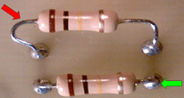
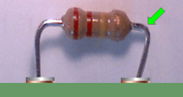
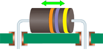
The component leads shall be bent such that the distance from the bend to the end seal shall be approximately equal at each end of the part, resulting in the centering of the part between the mounting holes.

NASA-STD-8739.3 [8.1.6.a]

UNACCEPTABLE

IMPROPER CENTERING

The component leads shall be bent such that the distance from the bend to the end seal shall be approximately equal at each end of the part, resulting in the centering of the part between the mounting holes.

NASA-STD-8739.3 [8.1.6.a], [13.6.2.a.5]

lead forming and bend radius improper bend radius

ACCEPTABLE

LEAD FORMING-BEND RADIUS

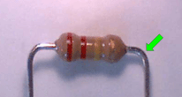
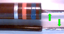
The radiius of bends in the conductor shall not be less than the lead diameter or lead thickness.

NASA-STD-8739.3 [8.1.6.a]

UNACCEPTABLE

IMPROPER BEND RADIUS

The radius of bends in the conductor shall not be less than the lead diameter or lead thickness.

NASA-STD-8739.3 [8.1.6.a], [13.6.2.a.10]

lead forming and bend spacing improper lead spacing

ACCEPTABLE

LEAD FORMING-BEND SPACING

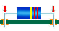
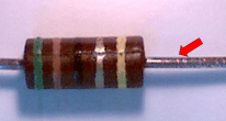
The minimum distance from the part body or seal to the start of the bend in a part lead shall be a minimum of 2 lead diameters for round leads, and 0.5 mm (0.020 in.) for ribbon leads.

NASA-STD-8739.3 [8.1.6.a]

UNACCEPTABLE

IMPROPER LEAD/BEND SPACING

The minimum distance from the part body, seal or weld bead to the start of the bend in a part lead shall be a minimum of 2 lead diameters for round leads, and 0.5 mm (0.020 in.) for ribbon leads.

NASA-STD-8739.3 [8.1.6.a], [13.6.2.a.15]

NASA WORKMANSHIP STANDARDS
NASA logo Released:
06.27.2002
Revision:
Revision Date:
Book:
6
Section:
6.02
Page:
2


THROUGH-HOLE SOLDERING
PREPARATION OF CONDUCTORS (cont.)
smooth tool marks reduced cross sectional area

ACCEPTABLE

LEAD FORMING-SMOOTH TOOL MARKS

Smooth tool impression marks resulting from tool holding forces are acceptable, provided they do not expose base metal or reduce cross-sectional area.

NASA-STD-8739.3 [7.2.3], [8.1.6.d]

UNACCEPTABLE

REDUCED CROSS-SECTIONAL AREA

Part leads and other conductors that have deformation/damage resulting in a reduced cross-sectional area shall not be used.

NASA-STD-8739.3 [7.2.3], [8.1.6.d]
NASA-STD-8739.4 [10.1.3]

preforming improper preforming

ACCEPTABLE

PREFORMING/SIZING

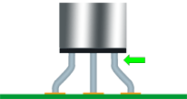
Part leads shall be formed so that they may be installed into the holes in the PWB without excessive deformation that can stress the part body or end seals. All leads should be tinned and formed prior to mounting.

NASA-STD-8739.3 [8.1.6.b], [8.1.6.c]

UNACCEPTABLE

IMPROPER PREFORMING/SIZING

Part leads shall be formed so that they may be installed into the holes in the PWB without excessive deformation that can stress the part body or end seals.

NASA-STD-8739.3 [8.1.6.b], [8.1.6.c]

tinning improper tinning

ACCEPTABLE

TINNING-COVERAGE

The portion of stranded or solid conductors, or part leads shall be solder tinned and cleaned prior to attachment. The solder shall completely wet the conductor and exhibit 100% coverage.

NASA-STD-8739.3 [7.2.5], [7.2.6]
NASA-STD-8739.4 [10.1.5]

UNACCEPTABLE

IMPROPER TINNING (COVERAGE)

The solder shall completely wet the conductor and shall exhibit 100% coverage.

NASA-STD-8739.3 [7.2.5], [7.2.6], [13.6.2.a.3]
NASA-STD-8739.4 [10.1.5]

NASA WORKMANSHIP STANDARDS
NASA logo Released:
06.27.2002
Revision:
Revision Date:
Book:
6
Section:
6.02
Page:
3


THROUGH-HOLE SOLDERING
PREPARATION OF CONDUCTORS (cont.)
tinning improper tinning

ACCEPTABLE

TINNING-DIMENSIONS

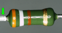
Hot tinning of solid conductors and part leads shall not extend closer than 0.5 mm (0.020 in.) to part bodies, end seals or insulation, unless the part configuration and mounting configuration dictate.

NASA-STD-8739.3 [7.2.5.a]

UNACCEPTABLE

IMPROPER TINNING (SPACING)

The tinning has extended closer than 0.5 mm (0.020 in.) to the part body/lead seals, and may have compromised the hermetic seal.

NASA-STD-8739.3 [7.2.5.a], [13.6.2.a.3]

tinning tinning gold removal

ACCEPTABLE

TINNING-DIMENSIONS
(SPECIAL EXEMPTION)

In instances where conductor tinning is required to be closer than 0.5 mm (0.20 in.), the part body, end seals, or insulation shall be inspected for damage and results recorded.

NASA-STD-8739.3 [7.2.5.a]

ACCEPTABLE

TINNING-GOLD REMOVAL

Gold plating on all surfaces that become part of finished solder connection shall be removed by two successive tinning operations, or by other approved processes.

NASA-STD-8739.3 [7.2.5.c]

tinning stranded wire damaged insulation

ACCEPTABLE

TINNING-STRANDED WIRE

The solder shall completely wet the conductor, penetrate to the inner strands, and exhibit 100% coverage. Wire strands shall be distinguishable. Wicking of flux or solder shall be minimized.

NASA-STD-8739.3 [7.2.5], [7.2.6]
NASA-STD-8739.4 [10.1.5]

UNACCEPTABLE

DAMAGED INSULATION

After stripping and tinning, the conductor insulation shall not exhibit any damage, such as nicks, cuts or charring. Conductors with damaged insulation shall not be used.

NASA-STD-8739.3 [13.6.2.a.1]
NASA-STD-8739.4 [19.6.2.a.2]

NASA WORKMANSHIP STANDARDS
NASA logo Released:
06.27.2002
Revision:
Revision Date:
Book:
6
Section:
6.02
Page:
4


THROUGH-HOLE SOLDERING
PREPARTION OF CONDUCTORS (cont.)
solder cups damaged conductor

ACCEPTABLE

TINNING-TERMINALS/SOLDER CUPS

Terminals and solder cups shall be solder tinned, examined for damage, and cleaned prior to the attachment of conductors.

NASA-STD-8739.3 [7.2,5], [7.3.1], [7.3.2]

UNACCEPTABLE

DAMAGED CONDUCTOR-GENERAL

After removal of the conductor insulation and/or lead forming, the conductor shall not be nicked, cut or scraped to the point that base metal is exposed.

NASA-STD-8739.3 [13.6.2.a.8]
NASA-STD-8739.4 [19.6.2.a.1]

excessive wicking

UNACCEPTABLE

EXCESSIVE WICKING

The use of flux and the solder-tinning operation shall be controlled to limit wicking under the insulation.

NASA-STD-8739.3 [7.2.5]
NASA-STD-8739.4 [10.1.5]


NASA WORKMANSHIP STANDARDS
NASA logo Released:
06.27.2002
Revision:
Revision Date:
Book:
6
Section:
6.02
Page:
5


Click here for printable .pdf file for Section 602 Through-Hole Soldering Preparation of Conductors click here to download Adobe Reader Click here to email the author of the Pictorial Reference Handbook
Need a printed copy?
(May take a while to load.)

Requires Adobe Reader.
Need Adobe Reader?
Click here to download.
Questions? Suggestions?