THROUGH-HOLE SOLDERING
AXIAL COMPONENTS
axial components
AXIAL COMPONENTS

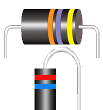
Axial-leaded components are often considered the most common type of discrete component used in through-hole printed wiring assembly.

See Section 6.01 "Through-Hole Soldering, General Requirements", for common accept/reject criteria.

horizontal mounting in non plated through hole horizontal mounting in non plated through hole

PREFERRED

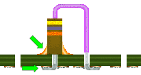
HORIZONTAL MOUNTING IN NPTH
COMPLETED ASSEMBLY

The component terminations are completely wetted. The solder fillets are smooth, nonporous, undisturbed, exhibit a concave profile and extend to the edge of the termination pad.

NASA-STD-8739.3 [13.6.1]

PREFERRED

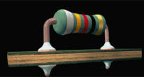
HORIZONTAL MOUNTING IN NPTH
INTERIM ASSEMBLY

Parts shall be parallel to and in full contact with the mounting surface, and centered between the termination holes. Leads shall be terminated with an off-the-pad-lap solder joint.

NASA-STD-8739.3 [8.4.2.a]

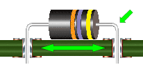
horizontal mounting in plated through hole horizontal mounting in non plated through hole

PREFERRED

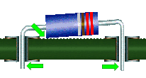
HORIZONTAL MOUNTING IN PTH
COMPLETED ASSEMBLY

The component terminations on both sides of the board are completely wetted. The solder fillets are smooth, nonporous, undisturbed, exhibit a concave profile and extend to the edge of the termination pad.

NASA-STD-8739.3 [13.6.1.f]

PREFERRED

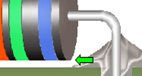
HORIZONTAL MOUNTING IN PTH
INTERIM ASSEMBLY

Parts shall be parallel to, and in full contact with the mounting surface and approximately centered between the termination holes. Leads exhibit proper stress relief bends and spacing.

NASA-STD-8739.3 [8.4.2.a]

NASA WORKMANSHIP STANDARDS
NASA logo Released:
06.27.2002
Revision:
Revision Date:
Book:
6
Section:
6.09
Page:
1


THROUGH-HOLE SOLDERING
AXIAL COMPONENTS (cont.)
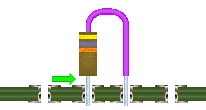
verticall mounting in plated through hole vertical mounting in plated through hole

PREFERRED

VERTICAL MOUNTING IN PTH
INTERIM ASSEMBLY

The component shall be mounted with a minimum of 0.5 mm (0.020 in.) to a maximum of 1.27 mm (0.050 in.) clearance between the end of the component and the board surface.

NASA-STD-8739.3 [8.4.2.b.1]

PREFERRED

VERTICAL MOUNTING IN PTH
COMPLETED ASSEMBLY

The component terminations on both sides of the board are completely wetted. The solder fillets are smooth, nonporous, undisturbed, exhibit a concave profile, and extend to the edge of the termination pad.

NASA-STD-8739.3 [13.6.1]

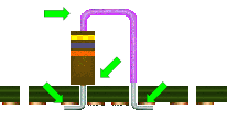
vertical mounting in non plated through hole vertical mounting in non plated through hole

PREFERRED

VERTICAL MOUNTING IN NPTH
INTERIM ASSEMBLY

The component shall be mounted with the end in contact with the board surface, and shall be terminated with an off-the-pad-lap solder joint. The opposite lead shall have 2 right angle bends.

NASA-STD-8739.3 [8.4.2.b.2]

PREFERRED

VERTICAL MOUNTING IN NPTH
COMPLETED ASSEMBLY

The component terminations are completely wetted. The solder fillets are smooth, nonporous, undisturbed, exhibit a concave profile and extend to the edge of the termination pad. The component is staked.

NASA-STD-8739.3 [13.6.1]

angularity in component position heat producing parts

ACCEPTABLE

ANGULARITY

Angularity shall not exceed 0.68 mm (0.025 in.), provided part of the component is in contact with the board, and the angularity does not violate minimum electrical spacing or lead protrusion requirements.

Best Workmanship Practice

ACCEPTABLE

HEAT PRODUCING PARTS

Parts which dissipate heat in quantities of 1 Watt or greater, or in quantities sufficient to damage the laminate shall be mounted with sufficient standoff [ > 1.5 mm (0.060 in.) ] and shall be mechanically restrained.

Best Workmanship Practice

NASA WORKMANSHIP STANDARDS
NASA logo Released:
06.27.2002
Revision:
Revision Date:
Book:
6
Section:
6.09
Page:
2


THROUGH-HOLE SOLDERING
AXIAL COMPONENTS (cont.)
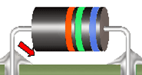
horizontal mounting gap improper horizontal spacing

ACCEPTABLE

HORIZONTAL MOUNTING
GAP

When parts will be bonded, slight spacing [ <0.68 mm (0.025 in.) ] will be acceptable. The part shall be mounted approximately parallel to the mounting surface.

NASA-STD-8739.3 [8.4.2.a]

UNACCEPTABLE

IMPROPER HORIZONTAL SPACING

Parts intended for horizontal mounting shall be parallel to, and in contact with, the mounting surface. Part spacing above the mounting surface should not exceed 0.68 mm (0.025 in.) unless the part will be bonded.

NASA-STD-8739.3 [8.4.2.a]
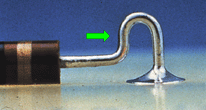
stress relief in component and solder connection insufficient stress relief in component and solder connection

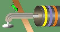
ACCEPTABLE

STRESS RELIEF

Stress relief shall be incorporated, wherever possible, into all leads and conductors in solder connections to provide freedom of movement of part leads or conductors between points of constraint. Camel-hump bend pictured.

NASA-STD-8739.3 [8.1.1]

UNACCEPTABLE

INSUFFICIENT STRESS RELIEF

Stress relief shall be incorporated, wherever possilbe, into all leads and conductors in solder connections to provide freedom of movement of part leads or conductors between points of constraint.

NASA-STD-8739.3 [8.1.1], [13.6.2.a.10]

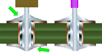
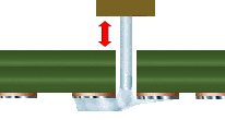
improper vertical mounting improper vertical mounting

UNACCEPTABLE

IMPROPER VERTICAL MOUNTING
NON-PLATED-THROUGH HOLE (NPTH)

The component has been mounted with a space between the component end and the board surface, eliminating any mechanical support to the part or solder joint.

NASA-STD-8739.3 [13.6.2.a.6]

UNACCEPTABLE

IMPROPER VERTICAL MOUNTING
PLATED THROUGH HOLE (PTH)

The component has been mounted with the end of the component in contact with the plated-through-hole (PTH). This will result in solder contact with the part body meniscus.

NASA-STD-8739.3 [8.4.2.b.1], [13.6.2.a.6]

NASA WORKMANSHIP STANDARDS
NASA logo Released:
06.27.2002
Revision:
Revision Date:
Book:
6
Section:
6.09
Page:
3


THROUGH-HOLE SOLDERING
AXIAL COMPONENTS (cont.)
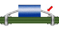
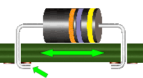
leads crossing exposed conductors

ACCEPTABLE

LEADS CROSSING EXPOSED CONDUCTORS

Leads crossing exposed conductors shall be sleeved with non-conductive sleeving or shrink tubing. Tubing shall be trimmed to meet insulation spacing requirements. Transparent/Translucent material is recommeneded.

Best Workmanship Practice


NASA WORKMANSHIP STANDARDS
NASA logo Released:
06.27.2002
Revision:
Revision Date:
Book:
6
Section:
6.09
Page:
4


Click here for printable .pdf file for Section 609 Through-Hole Soldering Axial Components click here to download Adobe Reader Click here to email the author of the Pictorial Reference Handbook
Need a printed copy?
(May take a while to load.)

Requires Adobe Reader.
Need Adobe Reader?
Click here to download.
Questions? Suggestions?