THROUGH-HOLE SOLDERING
SERVICE LEAD SPLICES
service lead splices
SERVICE LEAD SPLICES

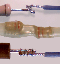
Design applications may require the termination of a discrete leaded component in a non-standard configuration, where the components are not terminated in the manner originally designed for the package type, the component's leads are being used as terminals, and/or where the termination method is not addressed in the NASA standards.

These terminations impose stress relief requirements on the solder joint and the component lead seals that must be addressed to ensure reliable operation.
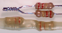
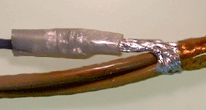
end splice ground lead wire splice

PREFERRED

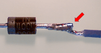
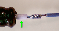
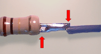
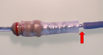
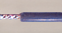
END SPLICE

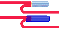
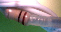
The end splice is a version of the lash splice, where the conductor ends are laid side by side, wrapped, soldered, and then insulated with shrink tubing. For inline configurations, the splice section may be bent back against the larger conductor(s) and sleeved for strain-relief.

PREFERRED

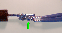
GROUND LEAD/DRAIN WIRE SPLICE

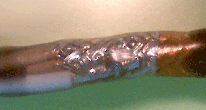
The lash splice can be used to attach a ground lead/drain wire to a shielded cable in instances where a solder sleeve is impractical or too bulky.
Assembly rating: Easy/Moderate
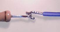
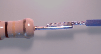
hook splice lap splice

PREFERRED

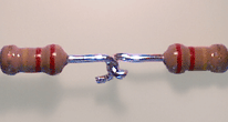
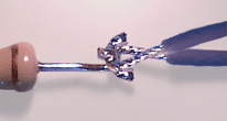
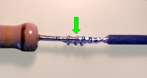
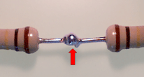
HOOK SPLICE

This splice is typically used to terminate discrete, leaded components in "daisy-chain" configurations. The termination has good tensile properties, but is prone to solder joint fatigue if repeatedly flexed.
Assembly rating: Easy

PREFERRED

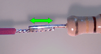
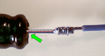
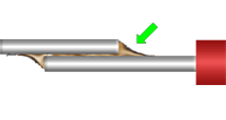
LAP SPLICE

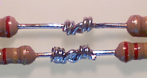
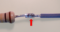
A lap splice is a non-structural splice, where the component lead end and the conductor end are soldered in parallel, overlapping contact to each other. The splice may be simple or complex, and is more compact than a solder sleeve.
Assembly rating: Easy

NASA WORKMANSHIP STANDARDS
NASA logo Released:
06.27.2002
Revision:
Revision Date:
Book:
6
Section:
6.16
Page:
1


THROUGH-HOLE SOLDERING
SERVICE LEAD SPLICES (cont.)
lash splice western union splice

PREFERRED

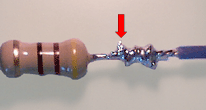
LASH SPLICE

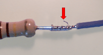
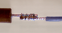
A lash splice is a structural splice, consisting of a lap splice with a single strand overlash winding mechanically binding the lead and conductor together. The splice may be simple or complex, and is more compact than a solder sleeve.
Assembly rating: Easy/Moderate

PREFERRED

LINEMAN/WESTERN UNION SPLICE

This splice is best suited for the termination of wire and cable, but can be used for the termination of discrete component leads. The splice is suitable for situations where the termination may be subjected to tensile loading.
Assembly: Difficult

magnet wire splice solder sleeve

PREFERRED

MAGNET WIRE SPLICE

After stripping and preparing for soldering, the ends of the wires shall be twisted together a minimum of three turns in an end slice configuration, soldered and insulated. The splice section shall be bent back against the larger conductor and strain-relieved.

PREFERRED

SOLDER SLEEVES

Originally developed for the termination of cable shield drain wires, solder sleeves produce a one-step, insulated and sealed splice. Solder sleeves are typically larger than that achievable with a lap or lash splice.

angular alignment lead misalignment

ACCEPTABLE

ANGULAR ALIGNMENT (LAP/LASH)

Angular misalignment of less than 2 lead diameters (measured at the conductor ends of the splice section) is allowable, provided there are no protruding or sharp edges.

Best Workmanship Practice

UNACCEPTABLE

LEAD/CONDUCTOR MISALIGNMENT

Angular misalignment in excess of 2 lead diameters (measured at the conductor ends of the splice section) produces a mechanically weak solder joint, with protruding ends or sharp edges.

Best Workmanship Practice

NASA WORKMANSHIP STANDARDS
NASA logo Released:
06.27.2002
Revision:
Revision Date:
Book:
6
Section:
6.16
Page:
2


THROUGH-HOLE SOLDERING
SERVICE LEAD SPLICES (cont.)
component lead insulation daisy chain

ACCEPTABLE

COMPONENT LEAD INSULATION

The component lead shall be sleeved with tubing, between the lead seal/weld bead to within 2 lead diameters of the solder joint (if applicable).

Best Workmanship Practice

ACCEPTABLE

DAISY-CHAIN

The components exhibit acceptable solder terminations and are sleeved to provide strain relief.

Best Workmanship Practice

conductor overlap excessive overlap

ACCEPTABLE

CONDUCTOR OVERLAP (LAP/LASH)

The conductors in the splice section shall be in parallel, overlapping contact to each other. The solder section shall be a minimum of 5-8 mm (0.2 - 0.3 in.) in length.

Best Workmanship Practice

UNACCEPTABLE

EXCESSIVE OVERLAP

The soldered section shall be a minimum of 5-8 mm (0.2 - 0.3 in.) in length, but should not contact the insulation jacket(s) or the lead seal/weld bead. Excessive overlap increases stress on the component lead and body seal/weld bead.

Best Workmanship Practice

hook splice orientation insulation gap

ACCEPTABLE

HOOK SPLICE ORIENTATION

The conductor and the component lead shall be aligned approximately 90º to, and in contact with, each other. In multiple conductor configurations, the direction of each additional conductor wrap shall be alternated, and shall not overlap.

Best Workmanship Practice

ACCEPTABLE

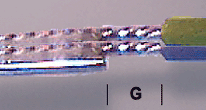
INSULATION GAP

The conductor(s) shall exhibit proper insulation spacing. In multiple conductor configurations, the conductor insulation gaps shall be approximately equal.

NASA-STD-8739.3 [9.1.1], [9.1.2]
NASA-STD-8739.4 [10.1.7.a]

NASA WORKMANSHIP STANDARDS
NASA logo Released:
06.27.2002
Revision:
Revision Date:
Book:
6
Section:
6.16
Page:
3


THROUGH-HOLE SOLDERING
SERVICE LEAD SPLICES (cont.)
insulation sleeving application exposed termination

ACCEPTABLE

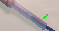
INSULATION SLEEVING APPLICATION

The completed solder joint shall be over-sleeved with transparent/translucent heat shrink tubing of sufficient length to cover the solder joint and extend over the insulation of each conductor a minimum of 5 mm (0.20 in.).

Best Workmanship Practice

UNACCEPTABLE

EXPOSED TERMINATION

The shrink tubing has been properly installed, resulting in exposure of the conductive surface. The tubing should be of sufficient length to cover the solder joint and extend over the insulation of each conductor a minimum of 5 mm (0.20 in.).

Best Workmanship Practice

lash winding improper lash wrap

ACCEPTABLE

LASH WINDING

The lash shall consist of a tinned, solid 34 AWG (or smaller) conductor, tightly wrapped in an open spiral of approximately 4-6 complete, non-overlapping turns, approximately centered over the splice. Lash ends shall be trimmed flush.

Best Workmanship Practice

UNACCEPTABLE

IMPROPER LASH/WRAP

The lash has been completed with a conductor the same gage as the mated conductors, resulting in an insufficient number of wraps to achieve a secure mechanical termination.

Best Workmanship Practice

lead seal bead spacing multiple configurations

ACCEPTABLE

LEAD SEAL/WELD BEAD SPACING

The component end of the solder joint shall not be closer than 2 lead diameters or 0.50 mm (0.020 in.), whichever is larger, from the lead seal/weld bead.

Best Workmanship Practice

ACCEPTABLE

MULTIPLE/COMPLEX CONFIGURATIONS

In multiple conductor configurations, the conductor ends may be twisted together, with the twisted section parallel to, and in contact with, the component lead.

Best Workmanship Practice

NASA WORKMANSHIP STANDARDS
NASA logo Released:
06.27.2002
Revision:
Revision Date:
Book:
6
Section:
6.16
Page:
4


THROUGH-HOLE SOLDERING
SERVICE LEAD SPLICES (cont.)
service lead solder fillet

ACCEPTABLE

SERVICE LEAD

The service lead conductor(s) shall be insulated stranded wire, unless otherwise specified in the engineering documentation.

Best Workmanship Practice

ACCEPTABLE

SOLDER FILLET

The solder joint shall comply with all the basic requirements of NASA-STD-8739.3 for a solder termination. The termination shall be fully wetted, with a smooth, shiny, concave fillet. The contour of the lead and conductor shall be discernable.

NASA-STD-8739.3 [13.6]

butt solder joint insufficient overlap

UNACCEPTABLE

BUTT SOLDER JOINT

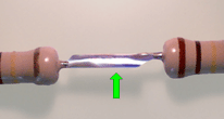
Butt solder terminations shall not be used.

Best Workmanship Practice

UNACCEPTABLE

INSUFFICIENT OVERLAP

The soldered section shall be a minimum of 5-8 mm (0.2 - 0.3 in.) in length to ensure the formation of a proper solder fillet, especially if a lap termination is used.

Best Workmanship Practice

protruding lash end splice located in flexure zone

UNACCEPTABLE

PROTRUDING LASH END

The end of the lash winding has not been properly trimmed, creating a potential short circuit problem.

Best Workmanship Practice

UNACCEPTABLE

SPLICE LOCATED IN FLEXURE ZONE

The termination shall not be located in a flexure zone.

Best Workmanship Practice

NASA WORKMANSHIP STANDARDS
NASA logo Released:
06.27.2002
Revision:
Revision Date:
Book:
6
Section:
6.16
Page:
5


Click here for printable .pdf file for Section 616 Through-Hole Soldering Service Lead Splices click here to download Adobe Reader Click here to email the author of the Pictorial Reference Handbook
Need a printed copy?
(May take a while to load.)

Requires Adobe Reader.
Need Adobe Reader?
Click here to download.
Questions? Suggestions?