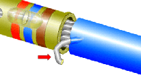
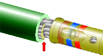
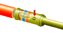
CRIMPED TERMINATIONS
GENERAL REQUIREMENTS
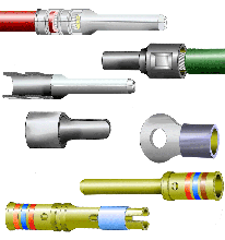
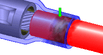
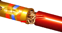
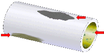
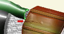
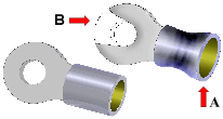
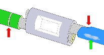
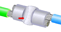
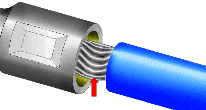
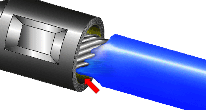
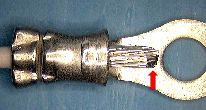
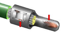
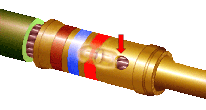
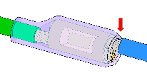
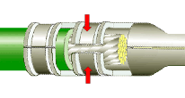
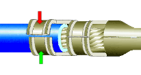
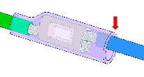
graphical representation of various crimps
Crimped Terminations

Crimping is an efficient and highly reliable method to assemble and terminate conductors, and typically provides a stronger, more reliable termination method than that achieved by soldering.

Crimp terminations are available in different styles, depending upon the design application and connectivity requirements.

This section details the generic accept/reject criteria of commonly used crimp termination styles. See 2.02 - 2.10 for specific accept/reject criteria applicable to individual crimp styles.
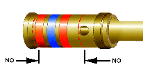
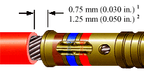
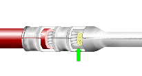
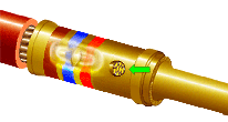
crimp indents placed properly crimp showing maximum insulation clearance

CRIMP LOCATIONS

(ALL CRIMP TYPES)

Crimp indents should be centered between the wire entry shoulder of the crimp barrel and the inspection hole/wire exit shoulder. Crimp indents shall not encroach on the wire entry shoulder or the inspection hole/wire exit shoulder.

MAXIMUM INSULATION CLEARANCE

(ALL CRIMP TYPES)

1. For conductors 20 AWG and smaller, the maximum clearance is 0.75 mm (0.030 in.).
2. For 18 AWG and larger conductors, the maximum clearance is 1.25 mm (0.05 in.).

NASA-STD-8739.4 [10.1.7.b.2], [19.6.2.c.9]
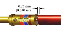
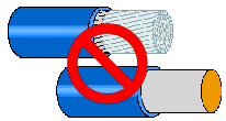
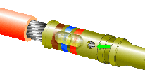
crimp showing minimum insulation clearance solder-tinned stranded and solid conductors with red mark over them to denote that crimping of this example is prohibited

MINIMUM INSULATION CLEARANCE

(ALL CRIMP TYPES)

The minimum insulation clearance for all crimped connections is 0.25 mm (0.010 in.).

NASA-STD-8739.4 [10.1.7.b.1], [19.6.2.c.9]

SOLDER-TINNED STRANDED WIRE

SOLID WIRE

Crimping of solid wire, component leads, or stranded wire that has been solder-tinned, is prohibited.

NASA-STD-8739.4 [4.3.4]

NASA WORKMANSHIP STANDARDS
NASA logo Released:
03.30.2001
Revision:
Revision Date:
Book:
2
Section:
2.01
Page:
1


CRIMPED TERMINATIONS
GENERAL REQUIREMENTS (cont.)
open barrel crimp with wire ends visible closed barrel crimp with wire strands visible

WIRE ENDS VISIBLE

(LUG/OPEN BARREL CRIMPS)

The wire ends shall be visible. The conductor should extend a minimum of even with, and a maximum of one wire diameter beyond, the conductor crimp edge.

Best Workmanship Practice

WIRE STRANDS VISIBLE

(PIN/CLOSED BARREL CRIMPS)

The wire strands shall be visible in the inspection hole, indicating that the conductor is properly inserted. Preferably, the wire end should be bottomed in the crimp barrel.

NASA-STD-8739.4 [19.6.1.c.3]

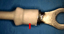
closed barrel crimp with wire ends visible crimp with acceptable heat shrink installation

ACCEPTABLE (MINIMUM)

WIRE ENDS VISIBLE
(PIN/CLOSED BARREL CRIMPS)

At a minimum, the ends of the wire strands shall be visible in the inspection hole, indicating that the conductor has been properly inserted in the crimp barrel.

NASA-STD-8739.4 [19.6.1.c.3]

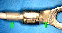
ACCEPTABLE

HEAT SHRINK INSTALLATION

Tubing is tight, symmetrical, undamaged (slight discoloration is acceptable). Overlaps meet minimum electrical spacing and provide strain relief. Termination is visible and inspectable.

NASA-STD-8739.4 [9.8.1], [9.9]

shrink tubing with acceptable slight discoloration crimp with birdcaged strands

ACCEPTABLE

DISCOLORATION

Slight discoloration of the shrink tubing is acceptable. Evidence of burning or charring is not acceptable.

Best Workmanship Practice

UNACCEPTABLE

BIRDCAGED STRANDS

Birdcaged strands reduce the conductor's overall strength and increase the possibility of shorting.

NASA-STD-8739.4 [19.6.2.c.3]

NASA WORKMANSHIP STANDARDS
NASA logo Released:
03.30.2001
Revision:
Revision Date:
Book:
2
Section:
2.01
Page:
2


CRIMPED TERMINATIONS
GENERAL REQUIREMENTS (cont.)
charred and split heat shrink contamination on crimp barrel

UNACCEPTABLE

CHARRED/SPLIT HEAT SHRINK

The heat shrink tubing has been exposed to excessive heat, resulting in charring and splitting of the sleeve and possible damage to the conductor. Slight discoloration is acceptable.

NASA-STD-8739.4 [9.8.1]

UNACCEPTABLE

CONTAMINATION

Tarnish, corrosion and/or contamination reduces the reliablity of the crimp contact.

NASA-STD-8739.4 [12.2.2], [19.6.2.c.8]

crimp barrel with cracks unacceptable modification of a crimp

UNACCEPTABLE

CRIMP BARREL CRACKS

Cracks in the crimp barrel reduce the mechanical reliability of the conductor-crimp termination.

NASA-STD-8739.4 [19.6.2.c.2]

UNACCEPTABLE

CRIMP MODIFIED TO FIT

Modifying the crimp, to accommodate an undersized/oversized conductor (A) or termination (B), reduces the mechanical strength and reliability of the conductor-crimp termination.

NASA-STD-8739.4 [4.3.5.a], [12.3.3], [19.6.2.c.6]

insulation with damage deformed crimp

UNACCEPTABLE

DAMAGED INSULATION

Cut, crushed, gouged, damaged or nicked insulation may result in reduced electrical isolation and/or short circuits. Slight scuffing or discoloration is acceptable.

NASA-STD-8739.4 [19.6.2.a.1]

UNACCEPTABLE

DEFORMED CRIMP

A damaged or deformed crimp indicates the use of an incorrect crimp positioner and/or improper insertion into the crimp tool.

NASA-STD-8739.4 [19.6.2.c.6]

NASA WORKMANSHIP STANDARDS
NASA logo Released:
03.30.2001
Revision:
Revision Date:
Book:
2
Section:
2.01
Page:
3


CRIMPED TERMINATIONS
GENERAL REQUIREMENTS (cont.)
disturbed lay of wire strands insulation whiskers extending into the conductor crimp section

UNACCEPTABLE

DISTURBED LAY

Disturbing the lay of wire strands during crimping may reduce the reliability of the crimp termination.

Best Workmanship Practice

UNACCEPTABLE

EDGE FLASH/INSULATION WHISKERS

Excessive edge flash or insulation whiskers that extend into the conductor crimp section may interfere with the proper mechanical and electrical termination of the crimp.

NASA-STD-8739.4 [19.6.2.c.10]

excessive conductor length exposed base metal on crimp barrel

UNACCEPTABLE

EXCESSIVE CONDUCTOR LENGTH

The conductor should extend a minimum of flush with, and a maximum of one (1) wire diameter beyond the conductor crimp edge.

Best Workmanship Practice

UNACCEPTABLE

EXPOSED BASE METAL

Exposed base metal reduces the reliability of the crimp.

NASA-STD-8739.4 [12.2.5], [19.6.2.c.6]

crimp improperly located over part of the inspection hole heat shrink length improper as it does not extend over the wire

UNACCEPTABLE

IMPROPER CRIMP LOCATION
(INSPECTION HOLE)

The indents shall not encroach on or distort the inspection hole.

NASA-STD-8739.4 [19.6.2.c.7]

UNACCEPTABLE

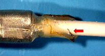
IMPROPER HEAT SHRINK LENGTH

Heat shrink tubing conforms to the crimp outline, but does not extend over the wire to provide any sealing or strain relief to the conductor.

NASA-STD-8739.4 [9.9]

NASA WORKMANSHIP STANDARDS
NASA logo Released:
03.30.2001
Revision:
Revision Date:
Book:
2
Section:
2.01
Page:
4


CRIMPED TERMINATIONS
GENERAL REQUIREMENTS (cont.)
incomplete conductor crimp incomplete insulation crimp

UNACCEPTABLE

INCOMPLETE CONDUCTOR CRIMP

An incomplete or improper conductor crimp will produce a conductor-crimp termination with reduced mechanical strength and reduced reliability.

NASA-STD-8739.4 [19.6.2.c.6]

UNACCEPTABLE

INCOMPLETE INSULATION CRIMP
(MULTIPLE CRIMP PINS/SOCKETS)

An incomplete or improperly set insulation crimp will produce a termination with reduced mechanical strength and reduced reliability.

NASA-STD-8739.4 [19.6.2.c.6]

incomplete heat shrinkage unacceptable opaque shrink

UNACCEPTABLE

INCOMPLETE SHRINKAGE

The heat shrink tubing conforms to the crimp outline and extends over the wire the proper length, but does not follow the contour of the wire, or provide any sealing or strain relief.

NASA-STD-8739.4 [9.8.1]

UNACCEPTABLE

OPAQUE HEAT SHRINK

Heat shrink tubing is opaque, prohibiting visual inspection of the termination. Heat shrink tubing shall be transparent or translucent, allowing visual inspection of termination.

Best Workmanship Practice

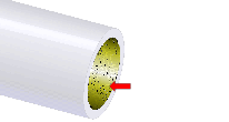
peeling and flaking of the plating on inside of crimp barrel protruding strands

UNACCEPTABLE

PEELING/FLAKING PLATING

A contact exhibiting peeling or flaking plating indicates a component of questionable quality and shall be rejected.

NASA-STD-8739.4 [12.2.3], [19.6.2.c.5]

UNACCEPTABLE

PROTRUDING STRANDS

Protruding strands reduce the current capacity of the termination, and present a puncture, sharp object damage or shorting risk.

Best Workmanship Practice

NASA WORKMANSHIP STANDARDS
NASA logo Released:
03.30.2001
Revision:
Revision Date:
Book:
2
Section:
2.01
Page:
5


CRIMPED TERMINATIONS
GENERAL REQUIREMENTS (cont.)
modified wires to fit the crimp barrel wire strands not visible in the inspection hole

UNACCEPTABLE

WIRE MODIFIED TO FIT

Modifying wires to fit the crimp barrel reduces the current carrying capacity and mechanical reliability of the conductor-crimp termination.

NASA-STD-8739.4 [4.3.5.a], [12.3.3], [19.6.2.a.2]

UNACCEPTABLE

WIRE STRANDS NOT VISIBLE
(PIN/CLOSED BARREL CRIMPS)

Wire strands not visible in the inspection hole indicate that the conductor may not be properly inserted and shall be cause for rejection.

NASA-STD-8739.4 [19.6.2.c.4]


NASA WORKMANSHIP STANDARDS
NASA logo Released:
03.30.2001
Revision:
Revision Date:
Book:
2
Section:
2.01
Page:
6


Click here for printable .pdf file for Section 201 Crimped Terminations General Requirements click here to download Adobe Reader Click here to email the author of the Pictorial Reference Handbook
Need a printed copy?
(May take a while to load.)

Requires Adobe Reader.
Need Adobe Reader?
Click here to download.
Questions? Suggestions?