SURFACE MOUNT TECHNOLOGY (SMT)
CHIP COMPONENTS BOTTOM-ONLY TERMINATIONS

chip components
CHIP COMPONENTS
BOTTOM-ONLY TERMINATIONS

The mechanical properties of the solder joints of bottom-only terminations are slightly reduced from those of 1-2-5 chip components, as only the metallized termination pads on the underside of the component are available for mechanical and electrical attachment tot he printed wiring board. The bottom only termination presents some difficulty during visual inspection, as very little of the actual termination is exposed or visible.

See Section 7.01 "Surface Mount Soldering, General Requirements", for common accept/reject criteria.

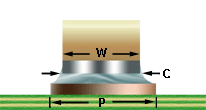
chip component end joint width

PREFERRED

The component is properly centered between the lands and exhibits acceptable solder thickness and tilt. No mechanical or heat damage is evident.

NASA-STD-8739.2 [12.9.1]

PREFERRED

END JOINT WIDTH (C)

The width of the end joint is equal to the width of the compoenent (W), and extends to the width of the land (P).

Best Workmanship Practice
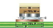
end joint width insufficient end joint width

ACCEPTABLE

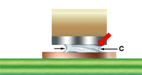
END JOINT WIDTH (C)

End joint width shall not be less than 75% of the component termination width (W) or less than 75% of the land width (P).

Best Workmanship Practice

UNACCEPTABLE

INSUFFICIENT END JOINT WIDTH (C)

An end joint of insufficient width indicates that there may be solderability problems that may adverely impact the long-term reliability and integrity of the solder termination.

Best Workmanship Practice

NASA WORKMANSHIP STANDARDS
NASA logo Released:
06.27.2002
Revision:
Revision Date:
Book:
7
Section:
7.04
Page:
1


SURFACE MOUNT TECHNOLOGY
CHIP COMPONENTS/BOTTOM-ONLY TERMINATIONS (cont.)
minimum fillet height maximum fillet height

ACCEPTABLE

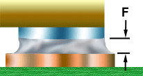
MINIMUM FILLET HEIGHT (F)

There shall be evidence of a properly wetted fillet on the exposed sides of the termination.

NASA-STD-8739.2 [12.9.1.a]

PREFERRED

MAXIMUM FILLET HEIGHT (E)

The fillet shall exhibit a positive wetting angle and shall not contact the component body.

NASA-STD-8739.2 [12.8.1], [12.8.2.b.12], [12.9.1.a]

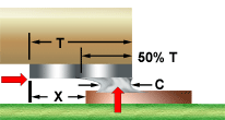
inside overhang inside overhang

PREFERRED

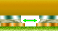
INSIDE OVERHANG

The target condiction is the component centered between the termination pads, without the inside edges of the metallized pads overhanging the edges of the termination pads.

NASA-STD-8739.2 [8.7.4.g.2]

ACCEPTABLE

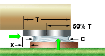
INSIDE OVERHANG (X)

Inside overhang (X) shall be less than or equal to 50% of the end termination width (T) and the minimum end joint width (C) requirements shall be met.

NASA-STD-8739.2 [8.7.4.g.2]

excess inside overhang end overhang

UNACCEPTABLE

EXCESS INSIDE OVERHANG (X)

Inside overhang shall not exceed 50% of the end termination width (T) and the minimum end joint width (C) requirements shall be met.

NASA-STD-8739.2 [12.6.2.a.2]

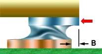
UNACCEPTABLE

END OVERHANG (B)

Overhang of the chip's metallization (pad) beyond the outside edge of the termination pad is not permitted.

Best Workmanship Practice
NASA WORKMANSHIP STANDARDS
NASA logo Released:
06.27.2002
Revision:
Revision Date:
Book:
7
Section:
7.04
Page:
2


SURFACE MOUNT TECHNOLOGY (SMT)
CHIP COMPONENTS/BOTTOM-ONLY TERMINATIONS (cont.)
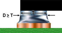
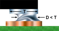
side joint length side joint length

PREFERRED

SIDE JOINT LENGTH (D)

The length of the side joint fillet equals or exceeds the component terminatio pad length (T).

Best Workmanship Practice
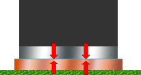
ACCEPTABLE

SIDE JOINT LENGTH (D)

Any side joint length is acceptable, provided there is evidence of a side joint, and all other joint parameters are met.

Best Workmanship Practice
side overhang side overhang

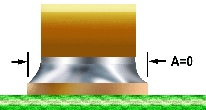
PREFERRED

SIDE/LATERAL OVERHANG (A)

The component is centered on the pads, with no side/lateral overhang (A).

NASA-STD-8739.2 [8.7.4.g.1]

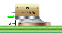
ACCEPTABLE

SIDE/LATERAL OVERHANG (A)

Side overhang shall not exceed 25% of the part width (W) and the minimum end joint width (C) requirements shall be met.

NASA-STD-8739.2 [8.7.4.g.1]

excess side overhang minimum solder thickness

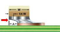
UNACCEPTABLE

EXCESS SIDE/LATERAL OVERHANG (A)

Side overhang in excess of 25% of the part width (W) and/or the minimum end joint width (C) may impact the long-term reliability and integrity of the solder termination.

NASA-STD-8739.2 [12.9.1.b.7]

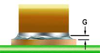
ACCEPTABLE

MINIMUM SOLDER THICKNESS (G)

The solder quantity shall be sufficient to form a properly wetted, concave fillet on the vertical surfaces of the chip, and which exhibits good wetting tot he chip metallization and termination pad.

NASA-STD-8739.2 [12.8.1.b], [12.9.1.a]

NASA WORKMANSHIP STANDARDS
NASA logo Released:
06.27.2002
Revision:
Revision Date:
Book:
7
Section:
7.04
Page:
3


SURFACE MOUNT TECHNOLOGY (SMT)
CHIP COMPONENTS/BOTTOM-ONLY COMPONENTS (cont.)
insufficient solder thickness tilt of component

UNACCEPTABLE

INSUFFICIENT SOLDER THICKNESS (G)

The solder quantity is insufficient to form a properly wetted, concave fillet which exhibits good wetting to the chip metallization and termination pad.

NASA-STD-8739.2 [12.9.1.b.5]

ACCEPTABLE
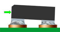
TILT

Part tilt shall be less than or equal to 25% of the part thickness, and shall not interfere with the proper placement of adjacent parts.

NASA-STD-8739.2 [12.6.2], [12.9.1]

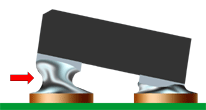
excess tilt of component

UNACCEPTABLE

EXCESS TILT

Part tilt in excess of 25% of the part thickness may impact the long-term reliability and integrity of the solder termination, and may interfere with the proper placement and thermal profile of adjacent parts.

NASA-STD-8739.2 [12.9.1.b.1], [12.9.1.b.2]


NASA WORKMANSHIP STANDARDS
NASA logo Released:
06.27.2002
Revision:
Revision Date:
Book:
7
Section:
7.04
Page:
4


Click here for printable .pdf file for Section 704 Through-Hole Soldering Chip Components/Bottom-Only Terminations click here to download Adobe Reader Click here to email the author of the Pictorial Reference Handbook
Need a printed copy?
(May take a while to load.)

Requires Adobe Reader.
Need Adobe Reader?
Click here to download.
Questions? Suggestions?