SURFACE MOUNT TECHNOLOGY (SMT) METALLIZED ELECTRODE FACE-MELF | |
![]() |
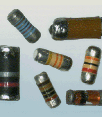
The Metallized Electrode Face (MELF) termination is characterized as a cylindrical package with metallized end caps, and is commonly used for the packaging of discrete diodes, capasitors and resistors. Since they are cylindrical, the MELF does nto have to be placed with the resistive elements facing away from the board surface, as is the case with rectangular chip packages. Like their through-hole axial cousins, MELFs are typically color-coded for value. |
![]() |
![]() |
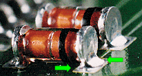
PREFERRED The termination exhibits a concave fillet on the terminal faces, with evidence of good wetting to the metallization and the periphery of the land. NASA-STD-8739.2 [8.7.4], [12.9.6] |
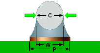
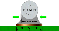
PREFERRED END JOINT WIDTH (C) The End Joint Width (C) shall be equal to or greater than the component width (W) or width of the land (P), whichever is less. Best Workmanship Practice |
![]() |
![]() |
ACCEPTABLE END JOINT WIDTH (C) The End Joint Width (C) shall be .50% of the component width (W) or width of the land (P), whichever is less. Best Workmanship Practice |
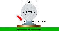
UNACCEPTABLE INSUFFICIENT END JOINT WIDTH (C) The width of the end joint shall not be less than 50% of the component termination width (W), or land width (P), whichever is less. Best Workmanship Practice |
NASA WORKMANSHIP STANDARDS | |||
![]() |
Released: 06.27.2002 |
Revision: |
Revision
Date: |
Book: 7 |
Section: 7.06 |
Page: 1 |
SURFACE MOUNT TECHNOLOGY METALLIZED ELECTRODE FACE - MELF(cont.) | |
![]() |
![]() |
PREFERRED END OVERLAP (J) The component should be positioned such that the termination caps are centered between the termination pads, resulting in fillet formation on all edges of the metallization. End overlap (J) should be greater than the termination cap length (T). Best Workmanship Practice |
ACCEPTABLE END OVERLAP (J) The termination cap shall overlap the land by at least 75% of the termination cap length (T). Example shows the inside edge of the termination cap even eith the land/pad edge, with end overlap (J) equal to the termination cap length. Best Workmanship Practice |
![]() |
![]() |
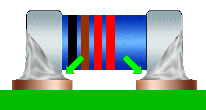
PREFERRED INSIDE OVERHANG The component is centered between the pads, with no portion of the termination cap overhanging the inside edges of the solder termination pads. NASA-STD-8739.2 [8.7.4.l], [12.9.6] |
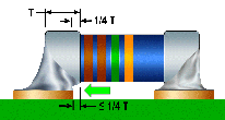
ACCEPTABLE INSIDE OVERHANG Inside overhang shall be less than or equal to 25% of the component termination length (T). NASA-STD-8739.2 [8.7.4.l], [12.6.2.a.8] |
![]() |
![]() |
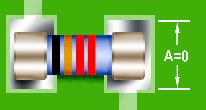
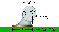
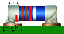
PREFERRED LATERAL/SIDE OVERHANG (A) The target condition is no lateral/side overhang, with the component centered on the land. NASA-STD-8739.2 [8.7.4.l] |
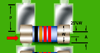
ACCEPTABLE LATERAL/SIDE OVERHANG (A) Lateral/side overhang (A) shall not exceed 25% of the component diameter (W) or land width (P), whichever is smaller. NASA-STD-8739.2 [8.7.4.l], [12.6.2.a.8] |
NASA WORKMANSHIP STANDARDS | |||
![]() |
Released: 06.27.2002 |
Revision: |
Revision
Date: |
Book: 7 |
Section: 7.06 |
Page: 2 |
SURFACE MOUNT TECHNOLOGY (SMT) METALLIZED ELECTRODE FACE - MELF (cont.) | |
![]() |
![]() |
UNACCEPTABLE EXCESS LATERAL/SIDE OVERHANG (A) The component shall not hang over the edge of the termination land by more than 25% of the component diameter area (W), or land width (P), whichever is less. NASA-STD-8739.2 [12.9.6.b.1] |
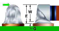
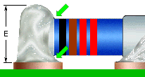
PREFERRED MAXIMUM FILLET HEIGHT (E) The maximum height of the solder fillet is 100% of the component diameter (W), plus solder thickness (G). The solder fillet exhibits full wetting, with positive angles, and does not extend over the top surface of the component cap. NASA-STD-8739.2 [12.9.6.a] |
![]() |
![]() |
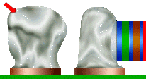
ACCEPTABLE MAXIMUM FILLET HEIGHT (E) The fillet may extend over the top of the end cap metallization, provided the fillet exhibits a positive wetting angle, and does not contact the part body. NASA-STD-8739.2 [12.9.6.a] |
UNACCEPTABLE TERMINATION CONTOUR IS NOT The contour of the termination shall be discernable in the solder fillet. NASA-STD-8739.2 [12.9.6.b.5] |
![]() |
![]() |
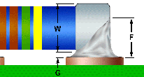
PREFERRED MINIMUM FILLET HEIGHT (F) The minimum height of the solder fillet shall be > 50% of the component diameter (W) plus the solder thickness (G), and shall extend the entire width of the part contact area. Best Workmanship Practice |
ACCEPTABLE MINIMUM FILLET HEIGHT (F) The solder thickness shall be sufficient to exhibit a properly wetted fillet, and complete solder flow under the component end cap. NASA-STD-8739.2 [12.8.1.b], [12.9.6.a] |
NASA WORKMANSHIP STANDARDS | |||
![]() |
Released: 06.27.2002 |
Revision: |
Revision
Date: |
Book: 7 |
Section: 7.06 |
Page: 3 |
SURFACE MOUNT TECHNOLOGY (SMT) METALLIZED ELECTRODE FACE - MELF (cont.) | |
![]() |
![]() |
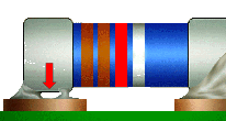
UNACCEPTABLE INSUFFICIENT SOLDER There shall be evidence of complete solder flow and wetting under the component end cap. NASA-STD-8739.2 [12.9.6.b.4] |
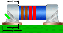
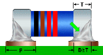
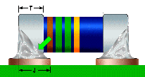
PREFERRED SIDE FILLET LENGTH (D) The side fillet should be equal to the End Termination Length (T), or Land Width (P), whichever is less. Best Workmanship Practice |
![]() |
![]() |
ACCEPTABLE SIDE FILLET LENGTH (D) The side fillet shall be greater than or equal to the End Termination Length (T) or land width (P), whichever is less. NASA-STD-8739.2 [12.9.6.b.2] |
UNACCEPTABLE INSUFFICIENT SIDE FILLET (D) The side fillet shall be > to 75% of the End Termination Length (T) or land width (P), whichever is less. Best Workmanship Practice |
![]() |
![]() |
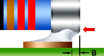
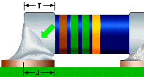
UNACCEPTABLE END OVERHANG (B) The end of the component termination cap should not extend beyond the outside edge of the termination pad. Best Workmanship Practice |
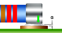
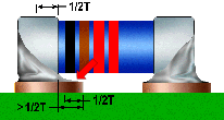
UNACCEPTABLE EXCESS INSIDE OVERLAP The component body should not overlap the termination pad in excess of 50% of the End Termination Length (T). Best Workmanship Practice |
NASA WORKMANSHIP STANDARDS | |||
![]() |
Released: 06.27.2002 |
Revision: |
Revision
Date: |
Book: 7 |
Section: 7.06 |
Page: 4 |
![]() |
![]() |
![]() |
Need a printed copy? (May take a while to load.) Requires Adobe Reader. |
Need Adobe Reader? Click here to download. |
Questions? Suggestions? |