SURFACE MOUNT TECHNOLOGY (SMT)
GULL-WING/"L" LEADED PACKAGES
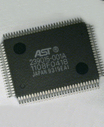
gull wing L leaded package
GULL-WING/"L" LEADED PACKAGES

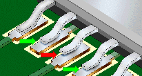
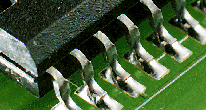
Gull-Wing IC package leads are formed in a profile very similar to the outline of a seagull's wings. The Gull-Wing is considered one of the most reliable terminations for fine-pitch, high pin-count packages.

"L" leaded IC packages have leads formed in a configuration very similar to the outline of the letter "L". The leads are shorter (length and height) than the "Gull-Wing" and tend to be much stiffer (hardened).

See Section 7.01 "Surface Mount Soldering, General Requirements", for common accept/reject criteria.
gull wing l leaded package coplanarity

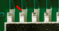
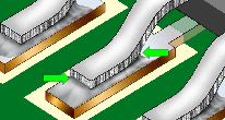
PREFERRED

The part is properly oriented to the land pattern, with each lead centered across the width of the land. Leads are planar, fillets are shiny and concave, and heel fillet is evident.

NASA-STD-8739.2 [8.7.4.h], [12.6.2], [12.8]

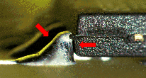
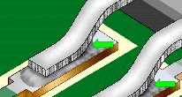
PREFERRED

COPLANARITY

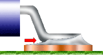
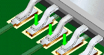
The preferred planarity of the lead to the land pattern area is with the foot parallel and in full contact with the pad.

NASA-STD-8739.2 [7.1]
coplanarity improper coplanarity

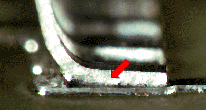
ACCEPTABLE

COPLANARITY

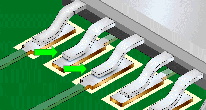
The maximum acceptable non-planarity between any portion of the lead foot and the pad shall not exceed 0.26 mm (0.010").

NASA-STD-8739.2 [7.1], [12.9.2.b.3]

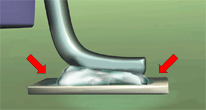
UNACCEPTABLE

IMPROPER COPLANARITY

The maximum acceptable non-planarity between any portion of the lead foot and the pad shall not exceed 0.26 mm (0.010").

NASA-STD-8739.2 [12.9.2.b.3]

NASA WORKMANSHIP STANDARDS
NASA logo Released:
06.27.2002
Revision:
Revision Date:
Book:
7
Section:
7.07
Page:
1


SURFACE MOUNT TECHNOLOGY
GULL-WING/"L" LEADED PACKAGES (cont.)
end joint width end joint width

PREFERRED

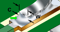
END JOINT WIDTH (C)

The width of the end joint (C) should be greater than or equal to the lead width (W).

Best Workmanship Practice

ACCEPTABLE

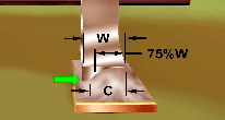
END JOINT WIDTH (C)

The width of the end joint shall be greater than or equal to 75% of the lead width (W).

Best Workmanship Practice

insufficient end joint width heel fillet

UNACCEPTABLE

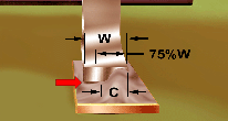
INSUFFICIENT END JOINT WIDTH (C)

The width of the end joint (C) is less than 75% of the lead width (W).

Best Workmanship Practice

MANDATORY

HEEL FILLET

A heel fillet is mandatory and the contour shall be positive.

NASA-STD-8739.2 [12.9.2.b.5]

missing heel fillet lateral overhang

UNACCEPTABLE

MISSING HEEL FILLET

A missing heel fillet is an indicator of improper process, and may impact the long-term reliability and integrity of the solder termination. A heel fillet is mandatory and the contour shall be positive.

NASA-STD-8739.2 [12.9.2.b.5]

PREFERRED

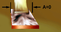
LATERAL/SIDE OVERHANG (A)

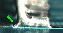
The target condition is no lateral/side overhang (A), with the component lead centered on the land.

NASA-STD-8739.2 [8.7.4.h], [12.6.2]

NASA WORKMANSHIP STANDARDS
NASA logo Released:
06.27.2002
Revision:
Revision Date:
Book:
7
Section:
7.07
Page:
2


SURFACE MOUNT TECHNOLOGY (SMT)
GULL-WING/"L" LEADED PACKAGES(cont.)
lateral overhang improper lateral overhang

ACCEPTABLE

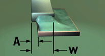
LATERAL/SIDE OVERHANG (A)

Lateral/side overhang shall not exceed 25% of the lead width (W), and shall not violate minimum electrical spacing requirements.

NASA-STD-8739.2 [8.7.4.h.l], [12.6.2.a.4]

UNACCEPTABLE

IMPROPER LATERAL/SIDE OVERHANG

Lateral/side overhang shall not exceed 25% of the lead width (W), and shall not violate minimum electrical spacing requirements.

NASA-STD-8739.2 [12.9.2.b.1]

maximum heel fillet height excess solder

ACCEPTABLE

MAXIMUM HEEL FILLET HEIGHT (E)

Solder may extend through the stress relief bend, but must not contact the lead seal. Solder shall exhibit a concave fillet and the lead contour shall be visible.

NASA-STD-8739.2 [12.8.1.b], [12.8.2.b.16]

UNACCEPTABLE

EXCESS SOLDER

The lead contour is not discernable; the solder extends through the stress-relief bends; and, the solder contacts the component body and seal.

NASA-STD-8739.2 [12.8.2.b.12], [12.8.2.b.16], [12.9.2.a.2]

minimum heel fillet height insufficient heel fillet height

ACCEPTABLE

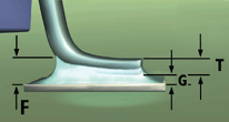
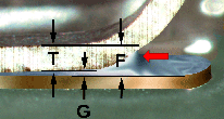
MINIMUM HEEL FILLET HEIGHT (F)

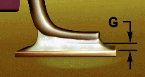
The fillet height shall be equal to or greater than the minimum solder thickness (G), plus one (1) lead thickness (T).

Best Workmanship Practice

UNACCEPTABLE

INSUFFICIENT HEEL FILLET HEIGHT (F)

The heel fillet height is less than the minimum solder thinckness (G), plus one (1) lead thickness (T). This may result in a weakened solder termination.

Best Workmanship Practice

NASA WORKMANSHIP STANDARDS
NASA logo Released:
06.27.2002
Revision:
Revision Date:
Book:
7
Section:
7.07
Page:
3


SURFACE MOUNT TECHNOLOGY (SMT)
GULL-WING/"L" LEADED PACKAGES (cont.)
side joint fillet side joint fillet

ACCEPTABLE

SIDE JOINT FILLET (D)

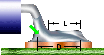
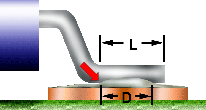
The side joint fillet (D) shall be present, equal to the lead width (W) plus the heel fillet, or equal to a minimum of 75% of lead length (L) plus the heel fillet, whichever is less, and exhibit complete wetting and a positive contour.

Best Workmanship Practice

UNACCEPTABLE

SIDE JOINT FILLET (D)

The side joint fillet shall be present, equal to the lead length (L) plus the heel fillet, and exhibit a positive contour.

NASA-STD-8739.2 [12.8.1.b]

solder thickness maximum solder

PREFERRED

SOLDER THICKNESS (G)

The solder thickness shall be sufficient to form a properly wetted, concave fillet which extends over the complete periphery of the connection.

NASA-STD-8739.2 [12.8.1.b], [12.9.2.a]

ACCEPTABLE

MAXIMUM SOLDER

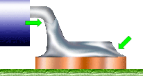
Solder quantity is at maximum, with the fillet extending up to the lead bend and completely covering the lead. The connection exhibits a well-wetted concave fillet on all sides, and the lead contour is discernable.

NASA-STD-8739.2 [12.8.1.b], [12.9.2.a]

minimum solder insufficient solder

ACCEPTABLE

MINIMUM SOLDER (B)

Solder quantity is minimum, but the connection is well wetted on all sides, with a concave fillet between the lead and the land. A heel fillet is evident and properly formed.

NASA-STD-8739.2 [12.8.1.b], [12.9.2.a]

UNACCEPTABLE

INSUFFICIENT SOLDER

The solder quantity shall be sufficient to form a properly wetted fillet.

NASA-STD-8739.2 [12.8.2.b.6]

NASA WORKMANSHIP STANDARDS
NASA logo Released:
06.27.2002
Revision:
Revision Date:
Book:
7
Section:
7.07
Page:
4


SURFACE MOUNT TECHNOLOGY (SMT)
GULL-WING/"L" LEADED PACKAGES (cont.)
nonwetting special exclusion improper wetting

ACCEPTABLE

NONWETTING
(SPECIAL EXCLUSION)

Leads not having wettable sides (edges) by design (such as leads stamped from pre-plated stock) are not required to exhibit side fillets.

Best Workmanship Practice

UNACCEPTABLE

IMPROPER WETTING

The solder fillet shall exhibit a positive wetting angle, wet all elements of the connection, and shall extend to the edge of the pad.

NASA-STD-8739.2 [12.9.2.a.1], [12.9.2.b.4]

toe overhang excessive toe overhang

ACCEPTABLE

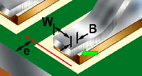
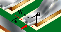
TOE OVERHANG (B)

Toe overhang (B) shall not exceed 25% of the lead width (W), and shall not violate minimum electrical spacing (e) requirements.

NASA-STD-8739.2 [8.7.4.h.2], [12.6.2.a.5]

UNACCEPTABLE

EXCESSIVE TOE OVERHANG (B)

Toe overhang (B) shall not exceed 25% of the lead width (W), and shall not violate minimum electrical spacing (e) requirements.

NASA-STD-8739.2 [12.6.2.a.4], [12.9.2.b.2]

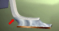
heel overhang

UNACCEPTABLE

HEEL OVERHANG

Heel overhang is prohibited.

Best Workmanship Practice

NASA WORKMANSHIP STANDARDS
NASA logo Released:
06.27.2002
Revision:
Revision Date:
Book:
7
Section:
7.07
Page:
5


Click here for printable .pdf file for Section 707 Surface Mount Technology (SMT) Gull-Wing/ click here to download Adobe Reader Click here to email the author of the Pictorial Reference Handbook
Need a printed copy?
(May take a while to load.)

Requires Adobe Reader.
Need Adobe Reader?
Click here to download.
Questions? Suggestions?